Monday 31 August 2015

4-meter band, a brief history lesson.


Clansman PRC 351.
Philips RT 4600/VRC.
History:
Before World War II, British radio amateurs had been allocated a band at 56 Mhz. After the war ended, they were allocated the 5-meter band (58.5 MHz to 60 MHz) instead. This only lasted until 1949, as by then the 5-meter band had been earmarked for BBC Television broadcasts.

In 1956, after several years of intense lobbying by the Radio Society of Great Britain (RSGB), the 4-meter band was allocated to British radio amateurs as a replacement for the old 5-meter band allocation. For several years the 4-meter band allocation was only 200 kHz wide--from 70.2 MHz to 70.4 MHz). It was later extended to today's allocation of 70.0 MHz to 70.5 Mhz.

Allocations:
A chart showing how Television channel frequencies in various countries relate to the 4 meter amateur band.
In addition to the traditional users (United Kingdom, Gibraltar and the British Military Bases in Cyprus), an increasing number of countries in Europe and Africa have also allocated the 4-meter band to radio amateurs as a result of the decline in VHF television broadcasts on the 4-meter band. Movement away from the old Eastern European VHF FM broadcast band and migration of commercial stations to higher frequencies have led to slow but steady growth in the number of countries where 4-meter operation is permitted.


Whilst not formally allocated at an ITU or Regional level, in Europe CEPT now recognizes the increased access to 70 MHz by radio amateurs with footnote 'EU9' which has helped underpin further growth. In July 2015 CEPT updated this footnote to fully recognize it as a formal secondary allocation:

"EU9: CEPT administrations may authorize all or parts of the band 69.9-70.5 MHz to the amateur service on a secondary basis."
In practice this ranges from 70 MHz to 70.5 MHz in the United Kingdom, with other countries generally having a smaller allocation within this window. In most countries the maximum power permitted on the band is lower than in other allocations to minimize the possibility of interference with non-amateur services, especially in neighbouring countries. A table with national and regional allocations is published and regularly updated on the Four Meters Website.

Propagation:
The 4-meter band shares many characteristics with the neighbouring 6-metre band. However, as it is somewhat higher in frequency it does not display the same propagation mechanisms via the F2 ionosphere layer normally seen at HF which occasionally appear in 6 meters, leastwise not at temperate latitudes. However, Sporadic E is common on the band in summer, tropospheric propagation is marginally more successful than on the 6-meter band, and propagation via the Aurora Borealis and meteor scatter is highly effective.

While Sporadic E permits Europe wide communication, it can be a mixed blessing as the band is still used for wide bandwidth, high power FM broadcasting on the OIRT FM band in a declining number of Eastern European countries. Although this has lessened in recent years, it can still cause considerable interference to both local and long distance (DX) operation.

First ever trans equatorial propagation (TEP) contact on 70 MHz took place on 28 March 2011 between Leonidas Fiskas, SV2DCD, in Greece and Willem Badenhorst, ZS6WAB, in South Africa.

Equipment and power:
Access to the 4-meter band has always been limited by access to suitable 4-meter transceivers. A limited number of transceivers were purposely built for amateurs on this band while converted Private Mobile Radio equipment is in widespread use e.g. Phillips FM1000 and the Ascom SE550. Some low power FM commercial equipment is available for the band although it is of relatively simple specifications as generally suitable for communication of up to around 50 kilometers (31 mi) or so with simple antennas.

Philips FM1000.

Ascom SE550.

In the Sporadic E seasons communication around Europe is possible with such equipment. Currently, the only Japanese-made, "mass-market" amateur radio transceiver to cover the Four meter band as standard is the Icom IC-7100, previously there was the UK specification Yaesu FT-847 which was discontinued in 2005. As a result, many 4-meter users gain access to the band by using converted "Low band" VHF ex-PMR (Private Mobile Radio) transceivers but invariably these only have either AM or FM and those users who prefer to have a multi-mode capability but can't afford a second hand Yaesu FT-847 normally use transverters, either purposely built home builds or sometimes even converted 6-meter or 2-meter versions.

In recent years there have been extensive imports of Chinese PMR transceivers such as the Wouxun KG-699E 4m (66-88 MHz) and KG-UVD1P1LV DUAL BAND (TX/RX 66-88 MHz / 136-174 MHz) Handheld Transceiver to Western countries mainly so far in the UK and mainland Europe. Qixiang Electronics, the makers of the AnyTone and MyDel transceivers, have exported the AnyTone 5189 PMR 4m Mobile, and the AnyTone 3308 Handheld (66-88 MHz) transceivers from China to the UK and to Europe. Both Transceivers have been selling extensively well in the UK and in Europe.

Recently (2014) a Monoband Multimode 70 MHz SSB/CW transceiver is released by NOBLE RADIO. Their website is www.nobleradio.eu.

Activity:
In some parts of the UK the band is little utilized, while in others, notably Belfast, Bristol, South Wales, North London and Hertfordshire, there is extensive local FM operation. There is considerable 4m activity along the east Coast of Ireland, mainly 70.400 FM. Also there are a number of Gateways/Links and Repeaters now operating on 4m which can be a handy form of FM Beacons. As band occupancy is relatively low, FM operation tends to take place on the calling frequency, 70.450 MHz, and AM operation on that calling frequency, 70.260 MHz. In the UK, the band is also used considerably for emergency communications, Internet Radio Linking Project links (IRLP), data links and low powered remote control.

In continental Europe the band is still primarily used for more serious DX operation. Cross-band working between the 6-meter band or the 10-meter band is common to make contacts countries where the band is not allocated.

Countries in which operation is permitted:

Bahrain (69.900-70.400 MHz)
Belgium (69.950 MHz center frequency, 70.190-70.4125)
Bulgaria (70-70.5 MHz)
Croatia (70.000-70.450 MHz)
Czech Republic (70.100-70.300 MHz)
Denmark (69.9875-70.0625, 70.0875-70.1125, 70.1875-70.2875, 70.3125-70.3875 and 70.4125-70.5125 MHz)
Estonia (70.140-70.300 MHz)
Faroe Islands (69.950-70.500 MHz)
Finland (70.000-70.300 MHz)
Åland Islands
Greece (70.200-70.250 MHz)
Greenland (70.000-70.500 MHz)
Hungary (70.000-70.500 MHz)
Ireland (Republic of) (70.125-70.450 MHz)
Italy (70.0875-70.1125, 70.1875-70.2125 and 70.2875-70.3125 MHz)
Luxembourg (70.150-70.250 MHz)
Monaco (70.000-70.500 MHz)
Namibia (70.000-70.300 MHz)
Netherlands (70.000-70.500 MHz)
Norway (70.0625-70.0875, 70.1375-70.1875, 70.2625-70.3125, 70.3625-70.3875 and 70.4125-70.4625 MHz)
Poland (70.1-70.3 MHz)
Portugal (70.1570-70.2125 and 70.2375-70.2875 MHz)
Azores
Madeira
Romania (70.000-70.300 MHz)
Slovakia (70.250-70.350 MHz)
Slovenia (70.000-70.450 MHz)
Somalia (70.000-70.500 MHz)
South Africa (70.000-70.300 MHz)
Spain (70.150 and 70.200 MHz)
UAE (70.000-70.500 MHz)
United Kingdom (70.000-70.500 MHz)[
Gibraltar
Guernsey
Isle of Man
Jersey
St. Helena
Countries with past or current experimental operation

In "experimental" countries, authorities authorized amateur radio experiments on the band for a limited period of time.

Germany (69.950 MHz center frequency)
Sovereign UK bases in Cyprus (70.000-70.500 MHz)

Other:
United States has one experimental transmitter in Virginia transmitting CW on 70.005 Mhz. Call sign is WE9XFT.
Glen Zook, K9STH, the Head Moderator of QRZ.com and a longtime magazine writer on VHF related topics, filed a petition with the U.S. Federal Communications Commission on 27 January 2010 to create a new U.S. 4-Meter amateur radio allocation at 70 MHz to parallel those in Europe and other parts of the world. [20] This petition was subsequently rejected by the FCC.
Common uses of the 4-meter band
FM Simplex
AM Simplex
Packet radio
SSB voice operation
Morse code (CW) operation
DX

Sunday 30 August 2015

70 MHz modifications for the ICOM IC-502 by Pino IK0SMG.


Prior to the release of 70 MHz by the Ministry of Communication for the experimental campaign I had already committed myself to this band.

After having completed a Yaesu FT 847 modification as extensively covered on the 4 m website for a friend of mine, I started building a 70 MHz to 28 MHz converter so that I could be on the band. As a subsequent project and with the help of some friends I began to build a prototype transverter based upon the DJ8S project as described in THE R.S.G.B RADIO COMMUNICATION HANDBOOK.

The prototype gave good results (pictures of modules) and after a long wait we were finally given access to the band last July! In the beginning, in order to get going properly, I tried to modify an IC-706Mk2G. Without altering other functions, things looked a bit difficult, the receiver was very deaf at 70 MHz but now works quite well, receive sensitivity is higher now having modified filters which before had a cut off frequency just above 50 MHz.

To achieve this, a microelectronic tool set is needed, mainly a magnifier or microscope. Needless to say, this modification for the ICOM is not for beginners but only for experienced and well equipped technicians.

Regarding the transmitter, I am still working on it, taking into consideration that above 60 MHz the transceiver switches digitally to V-UHF bands. A possible solution could be to use the HF-50 MHz PA to generate adequate RF power output.

To be operational on 4 m in good time, I decided to look for a modification of a simpler non digital transceiver. I considered many old 50 MHz rigs and I chose first an IC-201 for 2 m but I subsequently settled on the simpler IC-502A, brother of the well-known IC-202S.

To obtain one of these rigs was a bit of an adventure because when it was built 50 MHz was not allowed in Italy so it was never sold here. I looked on several Japanese web sites and found some at a reasonable price. Two units were bought, one for me and another one for IK0BZY along with an IC-3PS power supply and an IC-20L 10 W 144 MHz power amplifier.

The modification:

It is relatively easy to do!

Modify VFO range through some changes to capacitors and inductors so as to allow it to operate between 56-57 MHz, IF is at 13.9985 MHz as is the related VFO output filter.
Modify the receiver tuned input stage by replacing some capacitors and coil.
Modify mixer output filters towards TX PA stage. This is done by just replacing capacitors.
Modify tuned circuits of the TX- PA and output filters. This is also done by replacing capacitors.
Retune all stages.
Instruments used are: Signal generator, Power meter, Frequency counter.

All modified tuned circuits were simulated prior to implementation with RFSIM99 simulation software.

Nowadays the transceiver works within the original manufacturers specifications and it is very stable, the receive sensitivity is more than adequate.

It is an old rig, so you cannot expect precision frequency readout in order to use it for digital communication (WSJT) but for SSB/CW traffic, it is more than adequate. In any case, as with the IC -202S and other older transceivers, the importance of precision frequency readout at the time they were produced was not important.

It has an RF power output of 2-3 W and a whip antenna so it can be used for portable operation or as a PA exciter.


Power amplifier modification:

The next step was quite obvious really; in order to get a little bit more power (12 W) I modified the IC 20–L power amplifier. It was originally designed to operate on 144 MHz so to make it work on 70 MHz I once again recalculated and altered all of the input / output tuned stages and also the related output filter.


Now everything works fine and I am enjoying using it while studying the next stage of improvements for the IC-706MK2G or the transverter that I am about to complete.


Saturday 29 August 2015

Practical Wireless 70Mhz (4m) Contest.


Full rules will be published in the September 2015 issue of Practical Wireless (on sale early August). All entrants must read the complete published rules. The following summary is provided for convenience.
In brief:
  • Use ssb, cw, fm or am in the 70MHz (4m) band.
  • There are two sections:
  • Low Power - Transmitter output power limit 10 watts pep.
  • Open - Transmitter output power as per normal licence limit.
  • Date and duration as noted above.
  • Contest QSO exchange: RS(T) report, serial number starting 001, QTH locator.
  • Scoring: one point per contact, with multiplier = number of locator squares (e.g. IO91) worked.
  • The log must include at least one contact with a station in the United Kingdom or Eire.
  • Entries should preferably be sent by e-mail.
  • Paper logs sent by post are also accepted; these must be on A4 sheets, with first contact in each new square highlighted. Duplicate QSOs must be clearly marked.
  • Observe the band plan and avoid frequencies in use by non-contest activity, GB2RS, standard calling frequencies, etc.
  • You must provide all required covering information (see Rule 6 in the full rules), preferably using the online entry system or on a Cover Sheet if sent by post.
  • No repeater or satellite contacts.
  • Entries must be received either by e-mail or post to the address published in the rules by 20th October 2015.
The above is a brief summary and does not present all the conditions of the contest rules. You must read the full published contest rules before entering.
Contest stationery (log sheets and cover sheets) for paper entries are available for downloading here - just click the button.


Your contest log should be sent by e-mail to this address:

contest@pwpublishing.ltd.uk

Include your log file as an attachment.
The log file that you send should contain the same information that you would put in one sent on paper by post, except that you do not need to highlight the first contact in each locator square, nor do you need to mark duplicate contacts.
Files written by most popular contest logging software can be accepted including .LOG files from SDV or N1MM and REG1 .ADI files from MINOS. 

Keep it as simple as possible: a plain ASCII text file is just fine, so are spreadsheet files, etc..

 70MHz (4m) Excel Log Sheet70MHz (4m) Log Spreadsheet


When sending a file, please give it a file name that includes the callsign of your entry, e.g. G8EQX-P.XLS

You will receive an acknowledgement of your entry, normally within 24 hours of submitting it. If there is anything about your entry that gives problems (e.g. formatting), you will be contacted by e-mail.

If you haven't received a confirmation within 48 hours of sending a log by e-mail, please contact me at contest@pwpublishing.ltd.uk.

2. Send the covering information

You must also send the covering information required by Rule 6 (see full rules published in September Practical Wireless). The best way of doing this is to use this:

online contest entry system

Using this system not only reminds you to include all the required information, but also performs a number of checks on what you have entered before it is sent, helping to prevent errors. It also enters your information directly into the adjudicator's database, saving time and preventing errors. 
If for some reason you cannot use the online form, then send the Rule 6 covering information to the same e-mail address as the logs.

If you have any questions about this procedure, or other problems with sending your entry, please e-mail me at contest@pwpublishing.ltd.uk. 

Friday 28 August 2015

"FORKER" 5/8 over 5/8 Vertical for 70Mhz.

A highly efficient 2 x 5/8 wave FORKER Vertical antenna for the 70Mhz band with excellent wind handling ability and 5KW rated.

Justin Johnson G0KSC become well known for his LFA (Loop Fed Array) Yagi antennas with their exceptional low-noise performance. He has always been mindful of potential losses caused by matching devices and their placement within antennas. Some of the associated issues of matching devices include, power limitations on TX, noise induction on receive and alteration of the signal/antenna pattern.
This G0KSC designed 5/8 over 5/8 does not use any 'lossy' coils or traditional forms of matching devices. It uses a double-J arrangement or 2 vertical radials that run parallel to the main radiating element in order to achieve a balanced, 50 Ohm input. Unlike the J-pole which has a slightly directional pattern, the double-J or Fork type feed arrangement (hence the FORKER name!) produces an almost perfect symmetrical radiation pattern. This too can be seen in the plots listed in the 5/8 overview at the bottom of this page. Without traditional matching coils/devices, radiating efficiency remains higher than most competitive products.
The InnovAntennas 2 x 5/8 has been designed in order the pattern angles slightly downwards (11 degrees) in free space (above ground placement will alter this but radiation angle will remain low).This ensures even when this antenna is installed very high up, it will provide excellent near and far-field coverage.


The antennas are constructed with the best quality materials in order that the best mechanical construction can be achieved, not the cheapest and most profitable! Even a digital calliper is used (with an accuracy of .01mm) to measure the elements during production to ensure they are within tolerance, ensuring they work as well as our software model predicts.
1.    Marine grade Stainless Steel Fittings
2.    Original Stauff insulator clamps
3.    Mill finished for highest levels of accuracy

Performance:
Gain: 5.12dBi/2.97dBd @ 70.1MHz @ -11 degrees in free space
Gain @ 10m above ground: 8.41dBi/6.26dBd @ 4.2 degrees
Gain @ 20m above ground: 9.44dBi/7.29dBd @ 2.5 degrees
Maximum Power handling: 5KW
SWR: 1.02:1 @ 70.1Mhz - 1.5:1 @ 70Mhz - 1.5:1 @ 70.5Mhz (Centre frequency can be adjusted from 69.9 to 70.5Mhz with 2Mhz1.5:1 bandwidth
longest Section Length: 5.13m 
Weight: 4.52Kg 
Wind Loading: 0.1 Square Metres
Wind Survival: 160KPH 

Specification:
This antenna has been modelled both electromagnetically and mechanically in order to ensure it will stand up to adverse weather conditions very well. Both element diameter and wall thickness is tapered to ensure best possible survival characteristics and high quality components (including marine grade stainless steel A4/316 hardware) are used throughout. 
The 2 x 5/8wl FORKER vertical for 4m uses no coils or loading to ensure maximum radiated power. A solid rod delay-line is installed between the upper and lowers 5/8wl elements and the FORKER twin stubs at the base ensure this antenna has a 50 Ohm impedance.


Thursday 27 August 2015

28/70MHz transverter by Richard G6AKG .


I've finished my 28/70MHz transverter, later than I would have liked but I've been busy with other things.


Good news is a nice clean 12W output on 70MHz, with the second harmonic 40 dB down. Other sprogs noted at 84MHz are better than 40dB down too. The receive sensitivity is similar to that of the drive transceiver on 28MHz. However, there is a slight frequency skew in transversion of 6kHz but I can live with that for now.


Thanks to Serge UT5JCW of the Transverter Shop for his prompt help with technical queries.


So what next? Tackle putting LSB mode on PRS 320 manpack transceiver or finishing my QRP 30m beacon?
Added extras besides the two DPDT relays are the 30dB power attenuator on the left and small PCB, at the bottom of the picture, which is an RF activated switch option for the change over relay. The diecast box is an original Eddystone type purchased cheaply at a QRP Rally and the heat sink is from a scrapped single PCB industrial computer.

IRTS 70 MHz Continents, Countries and Islands (70 MHz CCI) Award Programme.


DEFINITIONS:
For the purposes of this document describing the 70 MHz CCI award programme the following terms shall have the following meanings.
“WAC”: means ‘Worked All Continents’, an award programme of the International Amateur Radio Union (IARU) which recognises amateur radio achievements in respect of communications with amateur stations located in the six continents of the world.
“DXCC”: means ‘DX Century Club’, an award programme of the American Radio Relay League (ARRL) which recognises amateur radio achievements in respect of communications with listed territories and entities around the world.
“DXCC Entity”: means an entry in the current DXCC list of territories and locations.
“IOTA”: means ‘Islands On The Air’, an award programme of the Radio Society of Great Britain (RSGB) which recognises amateur radio achievements in respect of communications with listed island groups around the world.
“IOTA Reference”: means an island group within the IOTA programme.
GENERAL IRTS issues CCI certificates to amateur radio stations around the world concerning international amateur radio communications in the 4m band.
The purpose of the CCI award programme developed by Dave Court, EI3IO is to recognise and promote DX achievements by amateur radio operators licensed to use frequencies in the range 69 – 74 MHz, (4 metres). In general the 4m band is limited to a relatively small but growing number of countries, mainly in Region 1 (Europe, Africa and the Middle East) and Region 2 (North America) of the International Telecommunication Union (ITU). 4m stations are or have been active in over 50 territories in Africa, Asia, Europe and North America.
A second objective is to stimulate an interest in the 4m band in countries which are not authorised to transmit in the range 69 – 74 MHz, by encouraging cross-band working to frequencies in the vicinity of 50.285 MHz and 28.885 MHz, which are recognised centres of cross-band activity.
IRTS reserves the right to amend the qualification criteria for the three levels of CCI award.
AWARD:
Three award levels, CCI, CCI century and CCI century plus are offered, based on the number of points obtained through:
In band two-way working of amateur and associated experimental radio stations located in continents, countries and islands in the 4m band or
Cross band working of amateur and associated experimental radio stations located in continents, countries and islands in the 4m band by two way in-band working, and for stations not authorised to use 4m, cross-band working to 4m from 6m or 10m, or a combination of cross-band and in-band working.
The awards will be designated In-Band or Cross-Band.
QUALIFICATION:
Qualification for a CCI award is based on an examination of a log extract and accompanying certification by the IRTS Awards Manager, which certifies that the applicant has made 70 MHz QSOs with amateur stations in the required number of continents, countries and islands. All log extracts must show the mode, must mention the 4m or 70 MHz band and if a cross-band QSO, in addition 6m (50 MHz) or 10m (28 MHz). Furthermore, the log extract must clearly show the DXCC entity and applicable IOTA reference, if an island. The following information should be helpful in determining the continent of a station located adjacent to a continental boundary. North America includes Greenland (OX). Asia includes, Cyprus (5B, ZC4). Europe includes the Azores (CU). Africa includes the Canary Islands (EA8), Ceuta & Melilla (EA9), Italian Islands (IH9 & IG9) and Madeira (CT3).
The rules for obtaining the award build on existing awards (WAC, DXCC and IOTA).
Point System1 2
A combination of WAC continents, DXCC countries and IOTA island groups which are not in the DXCC country list in their own right form the basis of the award. A continent is valid for 10 points (once only), an IOTA island reference which is not listed as a DXCC entity is valid for 2 points and a DXCC entity is valid for 1 point.
Example 1 An applicant works MJ3ABC (Island of Jersey) in IOTA reference EU-013. If this was the first European station worked 10 points would be gained as well as 1 point for Jersey (DXCC entity 122); a total of 11 points. As Jersey is already in the DXCC list its status as IOTA EU-013 is not applicable.
If MJ3ABC had been located on Les Minquiers Islands in IOTA reference EU-099, which is not in addition a named DXCC entity, stations working MJ3ABC would gain 2 points as an IOTA reference, plus another 10 points if this was the first QSO with the European continent.
Example 2 An applicant works OZ9XYZ located near Billund in Jutland (Jylland). Jutland is connected to the European mainland so it can count as 1 point for Denmark (DXCC entity 221).
If OZ9XYZ had been located in Copenhagen on the island of Sjaelland, IOTA reference EU-029 it would count for 2 points, even though Copenhagen is the capital city of Denmark.
1 The Azores has 3 IOTA references and is a single DXCC entity. For the purposes of the CCI award EU-003 will be considered as the DX entity and will count as 1 point for the Azores. IOTA References EU-175 and EU-089 will count for 2 points. The criteria invoked here is EU-003 hosts the Azore’s principal city.
2 Cape Verde has 2 IOTA references and is a single DXCC entity. For the purposes of the CCI award AF-005 will be considered as the DX entity and will count as 1 point for Cape Verde. IOTA Reference AF-086 will count for 2 points. The criteria invoked here is AF-005 hosts Cape Verde’s capital city.
Two other examples are provided in footnotes 1 and 2. In the case of query concerning the points applicable to any territory please contact the IRTS Awards Manager ( Awards at irts.ie ).
Points required for CCI awards
For the 70 MHz CCI in-band basic award 50 points are required, 65 for a cross-band award.
For the 70 MHz CCI in-band century award 100 points are required, 115 for a cross-band award.
For the 70 MHz CCI in-band century plus award 130 points are required, 145 for a cross-band award.
A 70 MHz CCI century plus award can also be endorsed for additional entities worked in steps of 20 e.g. +20, +40, +60 etc.
It is of course possible for stations licensed to transmit in the 4m band to hold both cross-band and in-band CCI awards.
QSO VALIDATION3:
A claim for an in-band or cross-band CCI Award and additional endorsements to a Century Plus award must be accompanied by a certified log extract (see below), to include date, time, frequency (in the case of a cross-band award), mode, station worked and claimed Continent and/or Country and/or Island.
CONDUCT:
All QSOs must be made with licensed amateur stations working in the authorised 4m allocation within the frequency range 69 – 74 MHz or with other stations licensed or authorised to communicate with amateur radio stations. Contacts made through repeaters or satellite transponders are not permitted for CCI credit. However Earth-moon-Earth (EME) QSOs are acceptable. In addition: All 4m operations should take place in accordance with the regulations pertaining in that jurisdiction. All stations contacted must be located on land. QSOs with maritime mobile and aeronautical mobile stations cannot be credited. All stations must be contacted from the same DXCC entity. All confirmations must be submitted exactly as received by the applicant.
It is a condition of the CCI award that the person applying unreservedly agrees: To observe all pertinent regulatory requirements for amateur radio in the country or countries concerned. To observe all rules applying to the CCI award process. To accept the decisions of the IRTS awards manager.
APPLICATIONS:
All applications shall be made electronically. An email shall be sent to the Awards Manager ( Awards at irts.ie ) which clearly indicates the category of in-band or cross-band CCI award requested (e.g. Basic, Century or Century Plus or endorsements to a Century Plus award) and the number of claimed continents, applicable IOTA references and DXCC entities to qualify for the award. The email address of the applicant should also accept incoming emails in case of a query. A log extract, shall be attached to the email certified as a correct extract from the claimant's log by an officer of a Radio Club or by two licensed radio amateurs. The log extract should also include details of the Continents, Islands and DXCC entities claimed
3 You may wish to ensure confirmations also include a QTH/Grid Locator as a 4m squares (MLA) award is also available.
for each QSO. The certification of the log extract may be attached to the email as a JPEG image of a scanned document.
Please address all correspondence and inquiries relating to CCI awards and all applications to the Awards Manager ( Awards at irts.ie )
FEES:

There are currently no charges levied for the issue of CCI awards and endorsements.

Wednesday 26 August 2015

Slim Jim and J-Pole calculator by John M3UKD.


The Slim Jim can be a great portable ‘roll up’ antenna, if made out of 300Ω or 450Ω ladder line / twin feeder. Add a loop of string to the top, and hang it on a tree branch, use it with your handheld transceiver, then roll it up and put it in your pocket when done! A Slim Jim for 2m (145MHz) will be 1.5 metres long, and 70cm (433MHz) will be 0.5 metres. Alternatively, for permanent installations, the copper tube or aluminium J-pole is a good choice. I have had good success with both, but regularly use the balanced feeder Slim Jim mounted on a 9m fibreglass pole, as can be seen in the photo at the bottom of the page.

It is recommended to use some sort of choke at the feedpoint. Around 6 close turns (for VHF) of the coaxial cable around a 40mm former (PVC pipe etc), or taped up and hung freely should be enough. I have also used a clip on ferrite for VHF. As with any balanced feed antenna, this will help prevent the braid of the coaxial cable from radiating, and becoming part of the antenna, and therefore affecting SWR and performance. The 6 turns is tested as adequate for VHF operation (145MHz) More may be needed lower down in frequency.

The spacing between elements, I have shown as 45mm on 2 metres. This is not critical. It will have some effect on where the 50Ω feed point is, but i’m sure you’ll find it! ‘D’ and ‘F’ work together in the calculations above. The critical lengths are B, C, and E then adjust the feedpoint to find a perfect match. Ignore B and E if building the "J pole".

*Velocity Factor: I have added the ability to select the velocity factor of your conductor. It is set by default to 0.96, which is for bare copper or bare aluminium. If you use balanced feeder such as 300Ω or 450Ω, adjust it to 0.91 (or set to the cable manufacturers specification if available).

50Ω feed point: The 50Ω feed point varies between the Slim Jim and the J-Pole. A Slim Jim has a higher feed impedance, due to it being a ‘folded dipole’, therefore it will be lower down. I have included a 50Ω feedpoint value for both the Slim Jim and the J-Pole, however, it really is a starting point and should be adjusted up and down until you get a 1.1 SWR with your antenna. You could even use a 4:1 coax balun and feed it higher up the matching section.

I made one for 4m (70MHz) which is 3 metres long. The quarter wave matching section can be made horizontal, with the half wave radiator section vertical, 90° to it if space is an issue, although this will affect radiation pattern slightly. Just remember the whole antenna needs to be in the clear, away from any objects, especially conductive objects!
So, how does this thing work?
Dipole Voltage Animation
Full Wave
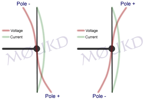
The Slim Jim, similar to the J-pole, is in fact a half wave end fed dipole, in the Slim Jim’s case, an end fed folded dipole. As with all folded dipoles, the currents in each leg are in phase, whereas in the matching stub they in phase opposition, so little or no radiation occurs from the matching section. You may think how can you say this is a dipole, when its just one element? Well, contrary to popular belief, the dipole is so named because it has two electrical poles, not two physical poles. Wouldn’t that be a di-element!? Just like a magnet has two magnetic poles, a North and a South, we have two electrical poles, a Positive and a Negative. Being a half wave, there is always two opposite poles on the tips at each half cycle. Any half wave antenna is actually a dipole.
To help explain this, I have drawn on the left, what happens to the voltage on a half wave element during one cycle. You can see, there are 2 poles, one positive and one negative at each half cycle. Hence, ‘dipole’. As its a half wave element, the wave is opposite at each end. Unlike the full wave example on the right, where the wave will join up if you imagine placing it on top of itself.
Hopefully, this explains things, and shows that the Slim Jim is actually a half wave dipole. A dipole, is usually fed from the centre, where the impedance is about 70Ω. This provides a reasonable match to 50Ω coaxial cable, and is why the centre fed dipole is so widely used. A dipole can be fed anywhere along its radiator, for example, the windom is ‘off centre’ fed at the 200Ω point, and an end fed half wave will give a very high impedance of up to around 5000Ω.
Feedpoint
So, we are feeding this half wave antenna from a high impedance point, which needs to be matched to 50Ω
coaxial cable, and is where the ‘J Integrated Matching’ (JIM) quarter wave matching section (λ/4) comes in. With the Slim Jim, you have the option to select the exact impedance you want, typically 50Ω. With the centre fed dipole, you have an impedance of around 68Ω, and usually the antenna is slightly detuned, to bring it down to 50Ω. The matching section is just that, and does not radiate significantly. Radiation starts from the beginning of the half wave section, to the tip of the antenna, so although the whole antenna is 3/4λ long, it is just a half wave radiator. The matching section does radiate a very small amount, due to the impedance’s at the top of the matching sections being not identical. This is because one is open (where the gap is) and the other is the feed for the radiating section. This means the two waves don’t completley phase each other out, and therefore some small radiation will occur. This is no significant problem, they are both high impedance, high voltage, low current points.
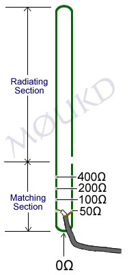
The 50Ω point can be found once you have built the antenna to the correct dimensions. Have the antenna out in the open, then move the feedpoint up and down small amounts, and when a 1:1 SWR is found, fix them there. An example of what the different impedance points may look like are shown on the image to the left. The calculator above will give you a good starting point, although spacing between the elements, velocity factor and other differences will have an effect on where this actually is.
Although the antenna is a half wave end fed, it will perform better than a half wave ground plane, due to its lower angle of radiation.
Dave M0TAZ using a 450Ω feeder Slim Jim on 70MHz.
I hope this has been of help to you. If you decide to build this antenna, I’d like to know what you think of it. Please leave a comment! Thanks, 73 John.

IRTS 70 MHz Maidenhead Locator Award (MLA) programme.


DEFINITIONS:
For the purposes of this document describing the 70 MHz Maidenhead Locator Award (MLA) programme the following terms shall have the following meanings.
“Maidenhead Locator (Locator)”: means the first four characters of the six character geographic coordinate system originally devised by Dr. John Morris, G4ANB, and approved by a group of IARU R1 VHF managers at a meeting in Maidenhead, England in1980. Maidenhead locators are also referred to as QTH Locators, Grid Locators or Grid Squares.
GENERAL IRTS issues MLA certificates to amateur radio stations around the world concerning international amateur radio communications in the 4m band.
The purpose of the MLA programme developed by Dave Court, EI3IO is to recognise and promote DX achievements by amateur radio operators licensed to use frequencies in the range 69 – 74 MHz, (4 metres). In general the 4m band is limited to a relatively small but growing number of countries, mainly in Region 1 (Europe, Africa and the Middle East) and Region 2 (North America) of the International Telecommunication Union (ITU). 4m stations are or have been active in over 50 territories in Africa, Asia, Europe and North America.
A second objective is to stimulate an interest in the 4m band in countries which are not authorised to transmit in the range 69 – 74 MHz, by encouraging cross-band working to frequencies in the vicinity of 50.285 MHz and 28.885 MHz, which are recognised centres of cross-band activity.
IRTS reserves the right to amend the qualification criteria for the three levels of MLA award.
AWARD:
Three MLA levels are available, the entry grade Half Century award, the Century award and the Double Century award are offered, based on the number of confirmed communication with stations in different Maidenhead locators by:
In band two-way working of amateur and associated experimental radio stations in the 4m band or Cross band working of amateur and associated experimental radio stations in the 4m band by two way in-band working, and for stations not authorised to use 4m, cross-band working to 4m from 6m or 10m, or a combination of cross-band and in-band working.
The awards will be designated In-Band or Cross-Band.
QUALIFICATION:
Qualification for a MLA is based on an examination of a log extract and accompanying certification by the IRTS Awards Manager, which certifies that the applicant has made 70 MHz QSOs with amateur stations in the required number of Maidenhead Locators. All log extracts must show the mode, must mention the 4m or 70 MHz band and if a cross-
band QSO, in addition 6m (50 MHz) or 10m (28 MHz). Furthermore, the log extract must clearly show the Maidenhead Locator claimed in its 4 or 6 character form.
Requirements for MLA Awards
For the 70 MHz MLA in-band Half Century award, communicating with stations in 50 locators is required, 75 for a cross-band award.
For the 70 MHz MLA in-band Century award, communicating with stations in 100 locators is required, 125 for a cross-band award.
For the 70 MHz MLA in-band Double Century award, communicating with stations in 200 locators are required, 250 for a cross-band award.
A Double Century Award can also be endorsed for additional locators worked in steps of 50 e.g. 250, 300, 350 etc.
It is of course possible for stations licensed to transmit in the 4m band to hold both cross-band and in-band MLA awards.
QSO VALIDATION:
A claim for all in-band or cross-band MLA awards and additional endorsements to a Double Century award must be accompanied by a certified log extract (see below), to include date, time, frequency (in the case of a cross-band award), mode, station worked and Maidenhead locator.
CONDUCT:
All QSOs must be made with licensed amateur stations working in the authorised 4m allocation within the frequency range 69 – 74 MHz or with other stations licensed or authorised to communicate with amateur radio stations. Contacts made through repeaters or satellite transponders are not permitted for MLA credit. However Earth-moon-Earth (EME) QSOs are acceptable. In addition: All 4m operations should take place in accordance with the regulations pertaining in that jurisdiction. All stations contacted must be located on the surface of the Earth. QSOs with aeronautical mobile stations cannot be credited. Stations located in ‘wet Maidenhead Locators’ by means of stations located on off-shore platforms or maritime-mobile stations installed on boats, ships or other floating objects can be credited. All stations must be contacted from the same locator.
It is a condition of the MLA award that the person applying unreservedly agrees: To observe all pertinent regulatory requirements for amateur radio in the country or countries concerned. To observe all rules applying to the MLA award process. To accept the decisions of the IRTS awards manager.
APPLICATIONS:
All applications shall be made electronically. An email shall be sent to the Awards Manager ( Awards at irts.ie ) which clearly indicates the category of in-band or cross-band award required (e.g. Half Century, Century, Double Century or endorsements to a Double Century award) and the number of claimed Maidenhead Locators to qualify for the award. The email address of the applicant should also accept incoming emails in case of a query. A log extract, shall be attached to the email certified as a correct extract from the claimant's log by an officer of a Radio Club or by two licensed radio amateurs. The log extract should also
include the Maidenhead Locator claimed for each QSO. The certification of the log extract may be attached to the email as a JPEG image of a scanned document.
Please address all correspondence and inquiries relating to MLA awards and all applications to the Awards Manager ( Awards at irts.ie )
FEES:

There are currently no charges levied for the issue of MLA awards and endorsements.

Monday 24 August 2015

Alinco or Anytone??

Recently I bought an Anytone AT-588 70Mhz radio, now these radios have been on the market for a while now and are very popular.
Having 50 watts out on high power and a bigger brighter display than it's older brother the Anytone AT-5189,which I owned since December 2010 and served me well.
The new one has a signal meter which I have been missing out in the shack.
I know that there are many ex-pmr radios out there which have signal meters such as the Philips FM-1000 range, the Simoco SRM with the 9030 head,have one in my car!!! and I even got a digital signal meter to operate on the Simoco PRM-8030's, this shows digits "00" to "99" and 00 being the lowest and 99 being full scale!!!

Some local hams who are not familiar with the new Anytone AT-588 4m radio I bought and have been asking me how best to describe it and I always say it resembles an Alinco in it's layout and menu.
I had a look online and came across some Alinco photos (as I do not own an Alinco), below you will see comparative pictures of the Alinco and the Anytone.

I cannot compare the technical differences between them but just the physical similarities:
ALINCO DR-438 Front Panel (CLICK TO ENLARGE).
ANYTONE AT-588 Front Panel (CLICK TO ENLARGE).
Above you can see the Alinco and the Anytone, the button layout IS different but the chassis is the same, right down to the yellow sticker on the top!!


ALINCO DR-438 Circuit (CLICK TO ENLARGE).
ANYTONE AT-588 Circuit (CLICK TO ENLARGE).
ALINCO (CLICK TO ENLARGE).
ANYTONE (CLICK TO ENLARGE).
Above you will see the internal circuit boards of the two radios, I kid you not!!!! The top one is from the Alinco and the bottom one is from the Anytone. Also there is a "code" etched on to the circuit boards of both radios, these codes are on the boards at the back of the radios to the left of the antenna socket.
I have also enlarged the pictures of the codes and as you can see they are very similar indeed!!

Below are two pictures of the rear of the radios, again identical, right down to the threaded hole in the middle of the heatsink....
ALINCO DR-438 Heatsink (CLICK TO ENLARGE).
ANYTONE AT-588 Heatsink (CLICK TO ENLARGE).
So there you have it, make your own mind up on them, but I think that the Anytone company must have purchased a batch of chassis and circuit boards to use on their own radios from Alinco...