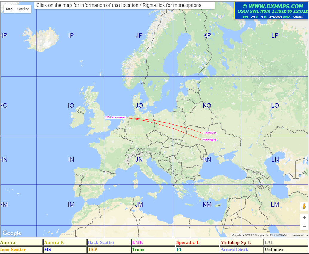
Keep an eye out via the following link:
https://www.dxmaps.com/spots/mapg.php?&HF=N&ML=M&Frec=70&Map=EU

 |
| C37MS. |

 |
| Jean-Jacques, ON7EQ. |


 |
| Picture of my 9030 plus control head which I use on my SRM9000 in car on 2m. |


 |
| EI4FMG on test in my Shack. |
 |
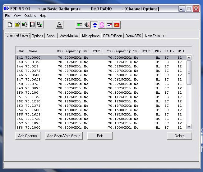
| Tait TM8110, Altai 5-7amp Power supply, EI4JR interface. |
 |
| On test. |

 |
| Shelving unit made by Jarek. |
 |
| New shack layout. |


|
70MHz UKAC
|
|||||
|
Date
|
29 Mar
16
|
Time
|
1900-2130
(UTC)
|
||
|
Date
|
31 May
16
|
Time
|
1900-2130
(UTC)
|
||
|
Date
|
30 Aug
16
|
Time
|
1900-2130
(UTC)
|
||
|
Date
|
29 Nov
16
|
Time
|
2000-2230
(UTC)
|
||
|
Band
|
4m
|
||||
|
Exchange
|
RS(T),
Serial Number (starting at 001 on each date) and a 6 character (e.g. IO92JL)
locator
|
||||
|
Scoring
|
One
Point per Kilometre multiplied by the sum of non UK Locator Squares worked
plus 2 times G, GW, GM, GI, GD, GU and GJ Locator Squares worked (M7)
|
||||
|
UK Contest Callsigns
|
Not allowed
|
||||
|
Sections
|
|||||
|
UKAC Open
(AO) |
Standard licence consitions and no antenna restrictions. |
||||
|
UKAC Restricted
(AR) |
The power output must be not more than 100W PEP (40W on 4m) at the final output stage or external amplifier connection to the antenna. Only one antenna may be used. Stacked or bayed antennas are not allowed. |
||||
|
UKAC Low Power
(AL) |
The power output must not exceed 10W PEP (4W on 4m) at the final output stage or external amplifier connection to the antenna. Only one antenna may be used Stacked or bayed antenna arrays may not be used. |
||||
|
General Rules
|
|||||
|
General
Rules for all RSGB VHF/UHF/SHF contests can be found here
|
|||||
|
Special Rules for this Contest
|
|||||
|
S8
|
These contests are timed to co-incide with the last two hours of a number of European activity contests, with an extra half hour at the end to encourage intra UK activity. They take place on Tuesdays from 2000-2230 local time with 144 MHz on the 1st Tuesday of the month, 432 MHz on the 2nd Tuesday, 1.3 GHz on the 3rd Tuesday, 50 MHz and 13cms to 3cms on the 4th Tuesday (due to Primary user restrictions, the 13cm event timings differ), and 70 MHz where there is a 5th Tuesday in the month. A UK station is required to be at one or both ends of a QSO for it to be valid. Please submit an entry after each session in which you are active. Scores will be normalised for each section in each session as follows. Score for each section/session = ((number of entrants+1)-(position of entrant))*1000/(number of entrants) The maximum number of sessions that will count towards the final individual scores will be EIGHT on all bands except 4m where it will be THREE. Only the lowest scoring entries are discarded. Note that ALL sessions count towards you club score. It is impossible for you to determine your best sessions without knowing everyone else's scores, so please submit your logs and scores from all sessions in which you were active and allow the adjudicator to calculate your best sessions. Stations may change section and move location between individual activity periods. Certificates will be awarded to the overall winners and runners-up in each section and on each band in the same way as per the general rules. No certificates will be awarded for the individual events. |
||||
|
S9
|
a. The individual entries by a club's members to the UK activity contests which take place on each Tuesday in every month all count towards a society's overall score for the year for each UKAC. To maximise the club score, it's important for the club contest organiser to get as many members to come on for as many sessions as possible. A rolling club listing will be maintained on the Contest Committee web site www.rsgbcc.org/vhf/results for each band. b. Stations enter the UKAC contests in the normal way, but need to choose an AFS (affiliated society) name when uploading their log. Entries to all sections of the UKAC count towards the overall club score which is the simple sum of the normalised scores of each team member operating that month. c. Stations who enter on behalf of an affiliated society must be members of the affiliated society, but not necessarily RSGB members themselves. d. All sessions will count towards the total club score. |
||||
|
Entries
|
|||||
|
Adjudicator
|
|
||||
|
Entry Date
|
Within
7 days after each activity period
|
||||
|
Log Entry
|
Upload
your log here
|
||||
|
Log Generator
|
Transcribe
your log online here
|
||||
|
Claimed Scores
|
Enter
your claimed score here
|
||||
|
Email Alerts
|
Set up
an Email Alert for this contest
|
||||

